Work on this kit was delayed, first by my trip to Wonderfest then by a deadline for a challenge project for a fall contest. Also slowing the project was the burning desire to make the eye functional. This was eased a bit by the then recently released lighting kit for the Knightrider car model. Of course, some modification to the lighting kit was going to be needed in order to make it work inside a solid resin figure kit. Further simplifying the process was an offer from Charlie Dunton (owner of Mad Dog Resin) of a clear resin head for those who wanted to attempt to light the eye. I don’t think Charlie ever expected anyone to do more than insert a light bulb or LED. As it turned out, it would have been more helpful if I had requested a clear leg instead of the head.

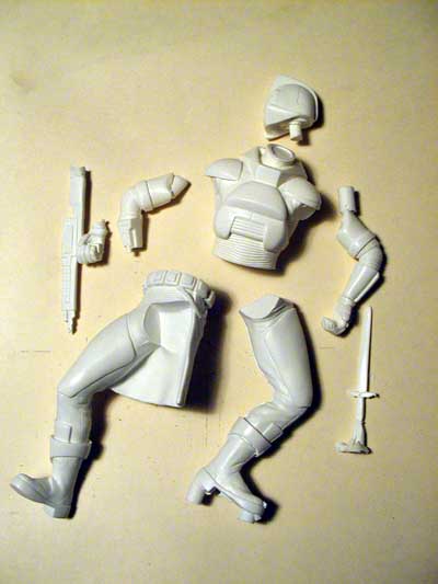
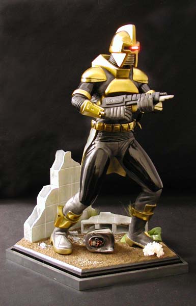
Ah, the Cylon Warrior…it was late in 2004 when I first became aware of this project by Mike Baldwin for Mad Dog Resin. I had only seen one other kit of this subject prior to this project. The other kit, while similar in size and pose, was not quite as dynamic and was a bit difficult to find. I knew I had to have this kit when it was released. That release date came about six months later and my order was placed in late April of 2005.
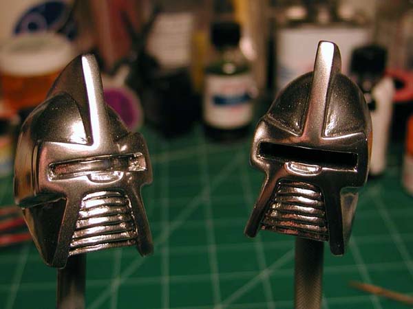
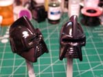
What I had originally envisioned was installing the lighting circuit in some sort of base that would also hold the power supply and then running a bundle of fiber optics through the leg, body, and head to the eye slit. This would require a large number of optics all arranged in proper order so that the “eye” would move smoothly across the field. This meant hollowing out the head and drilling a conduit through the torso and one of the legs. Here’s where the clear leg would have helped tremendously. Since each leg is bent at the ankle and knee, it was necessary to drill from both top and bottom with the bore meeting inside the knee joint. You can imagine the difficulty this presented in a solid piece of opaque resin. After a lot of VERY careful drilling and measuring I had a ¼” diameter hole from his heel to his waist. The torso and head were simple by comparison.
What I had originally envisioned was installing the lighting circuit in some sort of base that would also hold the power supply and then running a bundle of fiber optics through the leg, body, and head to the eye slit. This would require a large number of optics all arranged in proper order so that the “eye” would move smoothly across the field. This meant hollowing out the head and drilling a conduit through the torso and one of the legs. Here’s where the clear leg would have helped tremendously. Since each leg is bent at the ankle and knee, it was necessary to drill from both top and bottom with the bore meeting inside the knee joint. You can imagine the difficulty this presented in a solid piece of opaque resin. After a lot of VERY careful drilling and measuring I had a ¼” diameter hole from his heel to his waist. The torso and head were simple by comparison.
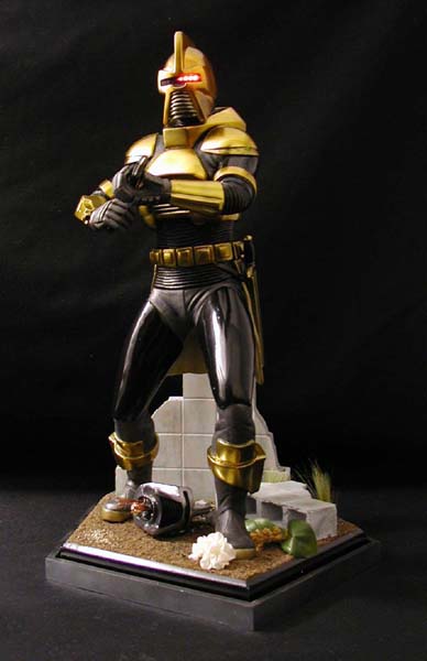
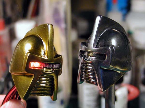
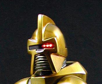
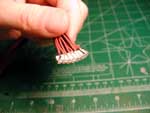
Fiber optics soon proved to be unmanageable. It would have required somewhere near 70 fibers (more if I had gone with the thinner strands I first envisioned). There was not enough flexibility with this large a bundle to handle the 90-degree bend inside the head. It was time for a new plan. Ah ha! Surface mount LEDs soldered to leads that would run through the body and connect to the circuit board in place the LEDs provided with the lighting kit. Eight LEDs would space properly across the eye slit and exactly match the number removed from the board. The ends of the leads were color coded so that the correct sequence could be established whenever I had to reconnect them to the circuit board for testing or prior to display. The eight LEDs in the eye slit were covered by a strip of transparent smoke acetate with two thin strips of black electrical tape on the reverse side to create the narrow slit within the eyepiece.
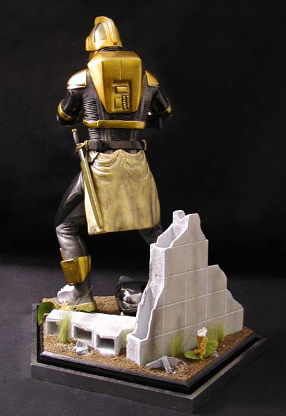
The figure was painted using a combination of Floquil lacquers, Alclad II lacquers, and Tamiya transparent paints. After a straightforward assembly and minor seam filling, the kit was covered in a gray primer. Over this came a coat of Floquil Graphite for the body suit. After masking, the raised armor plating was painted a Floquil Gloss Black (I’ve had my best success using this as the undercoat for the Alclad paints). Once the black had sufficient time to cure—approximately 24 hours—I applied the Alclad Chrome over the head, chest, belt, armbands, bracers, and boot tops. The rest of the armor was left gloss black. Over top of the Alclad I applied the transparent paints—a 2:1 mix of yellow and orange—building up the tone until I was satisfied with the gold effect. Lastly, the gold was finished off with a couple of coats of Future acrylic to restore the shine to the gold metallic. The ribbing on the chest and arms of the body suit were hand painted with gloss black. The skirt and soles of the boots were painted with Floquil Brass for contrast the metal. Shading was applied using Alclad transparent smoke.
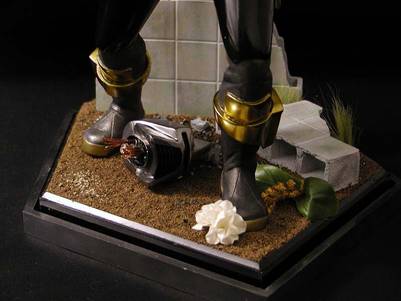
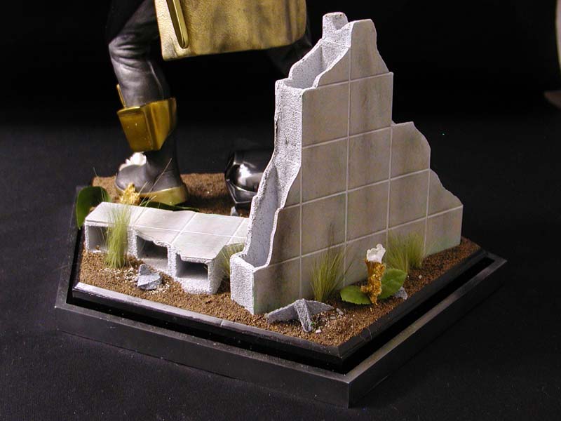
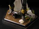
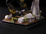
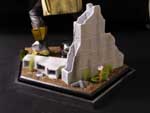
While all of the planning and fussing over the lighting and wiring was taking place I was also planning and building the custom base for the kit. I had to start this early in the project so that I could work out the power source and placement of the figure relative to the circuitry. The inspiration for the base came from the double pentagram symbol of the Cylons. If you look at it in plan view you will see that the inner base and surrounding chrome ridge form the concentric pentagrams. On the surface of the inner piece would be some rubble, groundcover, and a flower crushed under his foot. The block wall was made from floral foam hollowed out the represent concrete block. This was clad in sheet styrene embossed with a 1” square pattern. While I like the overall concept of the base, I feel the execution was too clean. Oh well…live and learn.


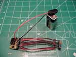
The sound effect was a late addition to the project. While it was something I had thought of early on, it wasn’t actually started until well into the project. A digital sound recorder purchased from Radio Shack was modified to play a continuous loop of the “Whoo, whoo” sound of the Cylon eye in motion. A larger speaker was substituted for the cheap one included with the soundboard and a jumper wire with an integral switch was attached across two points on the board. I chose to leave the lighting and sound independent of each other (save for a shared DPDT switch so that they could be turned on and off simultaneously). The speaker was mounted flush to the underside of the base beneath the block wall. That way I could cut a sound hole in the base that would be completely hidden by the details of the base.
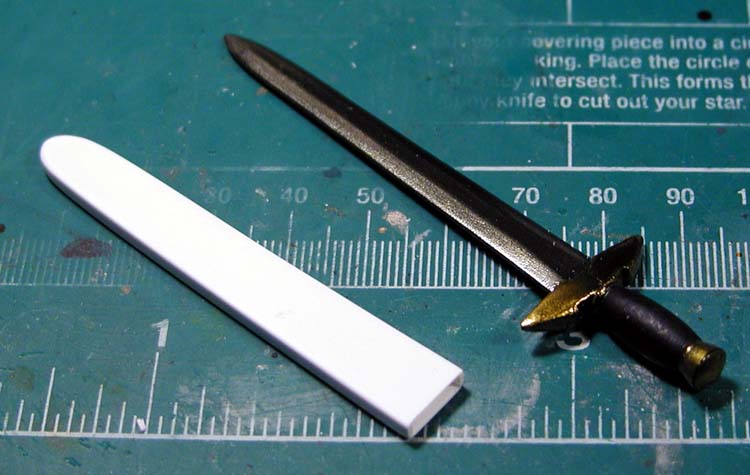
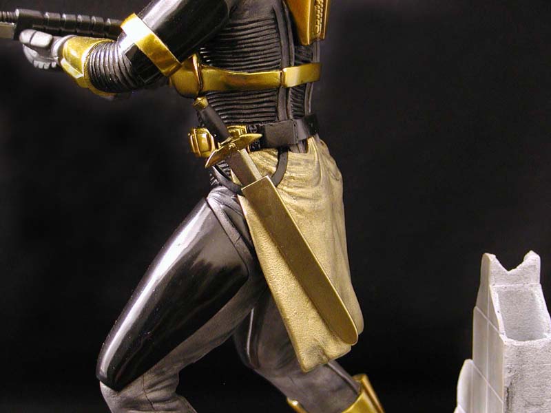
The final detail was the sword on the kit’s left hip. I wasn’t happy with the one that came with the figure—too irregular. I fashioned a new one out of styrene by shaping some stock into a sword blade and turning another piece to make the grip. These were attached to the cross guard from the original sword. Why did I keep the original guard after scratch building everything else? In hindsight, I don’t know. I had intended to only replace the blade at first, but things just kept going further and, well that’s just the way things turned out. The sheath was put together in about 30 minutes using some thin sheet stock and some styrene strips fashioned to fit snuggly around the blade. Painting the sword and sheath followed the techniques used on the figure.
Did I forget to mention some detail or describe some aspect of this project? Probably. If I did, and you have a question or two, feel free to ask me and I’ll get back to you with the answer. Who knows, I might even have sense enough to update the text here with the missing information.
I hope you like what I’ve created!
Click on picture for a movie of the eye in action!